
Electrical Design |
Tiva Launchpad pinout diagram
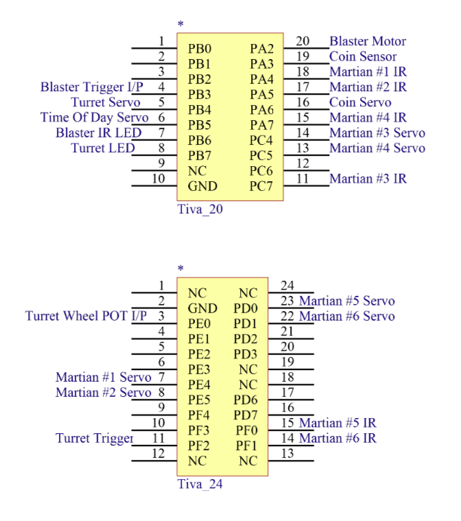
The LEDs and Servos were placed on the PWM outputs of the TIVA. For the triggers and buttons, the internal pull-up resistor was configured.
Token Sensing Circuit
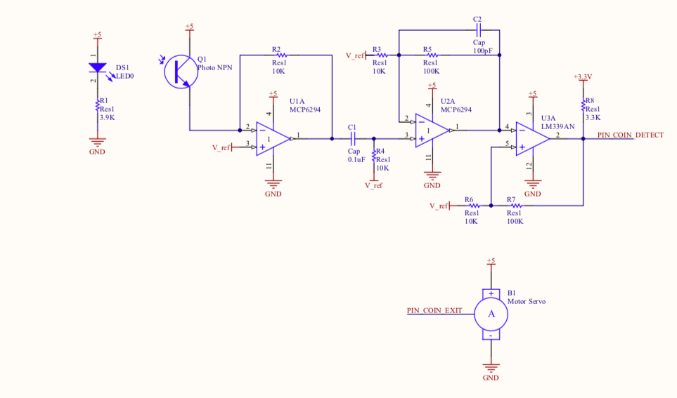
The token (TOT) sensing circuit consisted of a coin sensor which was effectively a beam break circuit with an IR emitter and photo transistor. The output from this signal was passed through a trans-resistive amplifier and then through a high pass filter. This signal then was amplified using an Op Amp and pulled to 3.3 V or 0 V using a comparator.
The token was help in place using a servo horn and was exited from the game when the 60 seconds of the game were up or thee 30 seconds of the idle timer expired.
The token was help in place using a servo horn and was exited from the game when the 60 seconds of the game were up or thee 30 seconds of the idle timer expired.
Alien Circuit
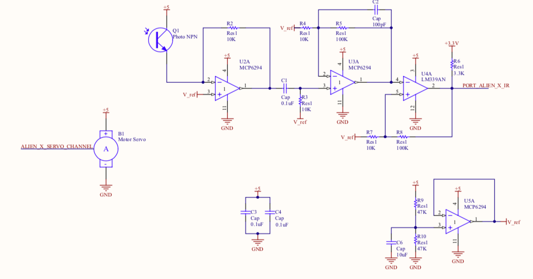
The aliens were mounting onto a Servo Motor which would change position when the alien was shot (IR detected).
The IR sensing circuit used on the alien is the same as the one used to detect the token and described in the above section.
The IR sensing circuit used on the alien is the same as the one used to detect the token and described in the above section.
Blaster Circuit
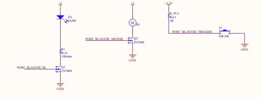
The blaster circuit had 3 components:
- The trigger was a limit switch which was configured with the internal pull up resistor on the TIVA
- The Emitter was an IR Led which was pulsed at a frequency of 100 Hz using the PWM pins on the TIVA through a MOSFET
- The Vibration Motor was controlled to vibrate every time the trigger was pressed via the MOSFET
Turret Circuit
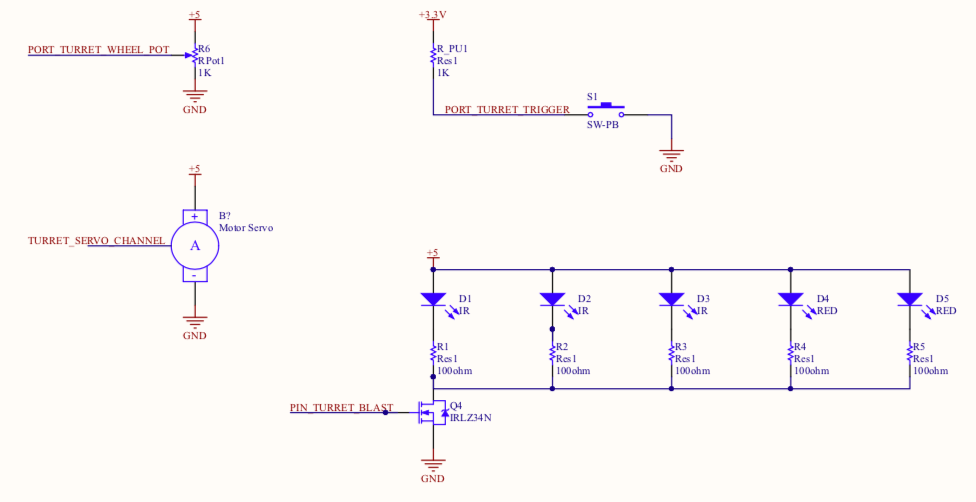
The Blaster circuit had 4 components:
- A potentiometer which controls the heading of the turret
- A servo which responds to the readings from the potentiometer
- IR LEDs and Red LEDs in Parallel and controlled by a MOSFET
- The trigger was a limit switch which was configured with the internal pull up resistor on the TIVA
- A potentiometer which controls the heading of the turret
- A servo which responds to the readings from the potentiometer
- IR LEDs and Red LEDs in Parallel and controlled by a MOSFET
- The trigger was a limit switch which was configured with the internal pull up resistor on the TIVA
